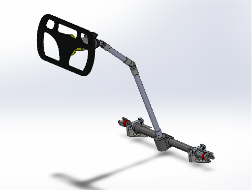
Formula SAE Steering System
Trimmed steering mass by 20% via rack mount redesign, reduced u-joint misalignment ~10° through procedural jigging, and refactored Ackermann geometry (~60–80%) from slip angle analysis.
Project Overview
As part of Northwestern Formula Racing, I contributed to the steering system for the NFR26 racecar. The goals were to maximize steering column stiffness and linearity while reducing binding, and to refine Ackermann geometry to optimize tire slip behavior across dynamic events at competition. The work spanned slip angle analysis, rack mount redesign for mass reduction, and a new jigging procedure to correct the misalignment issues that caused heavy steering in prior years.
Development Timeline
Phase 1: Steering Geometry & Ackermann Analysis
Analyzed tire lateral force vs. slip angle data across multiple vertical loads to inform steering geometry decisions. Refactored the geometry to target pro-Ackermann (~60–80%), prioritizing low-speed maneuverability for tight corners and the endurance event while maintaining stability at speed.
- Tire lateral force (FY) vs. slip angle (SA) curves analyzed at FZ = 50–250 lbs
- Pro-Ackermann geometry set at ~60–80% based on slip angle data
- Low-speed maneuverability prioritized for endurance and autocross
- Geometry tradeoff balanced against high-speed cornering stability

Phase 2: Rack Mount Redesign
Redesigned the steering rack mount to reduce total steering system mass by 20%. The lighter mount improved steering responsiveness by reducing rotating and reciprocating mass in the system, while maintaining structural integrity within the chassis envelope.
- 20% total steering system mass reduction
- Rack mount geometry redesigned in SolidWorks
- Reduced mass improved steering responsiveness
- Assembly packaged within chassis envelope constraints

Phase 3: U-Joint Alignment & Procedural Jigging
Designed a jigging setup for the pillow blocks to ensure proper placement before welding. Previous years lacked proper jigging, resulting in misaligned steering columns and "heavy" steering caused by u-joint binding under misalignment. The fixture constrained the column and rack during assembly, achieving approximately 10° less misalignment than the prior year and repeatable results across builds.
- Jigging fixture locates pillow blocks precisely before welding
- Prior years had no jigging — misaligned columns caused noticeably heavy steering
- ~10° reduction in u-joint misalignment versus prior year
- Repeatable assembly process documented for future builds

